A non-conductive flat board (generally fiberglass laminate) with conductive lines on one or more surfaces of the board. Note: This guide is intentionally basic, and is intended to be more useful for novice-to-beginner readers that are interested in researching and getting involved with the PCB industry, whether as a hobbyist or as an engineer. If you are just plunging into the world of electronics or Printed Circuit Boards, congratulations, and welcome! You’re in for a treat.
Some Basic Terms and Definitions
A basic understanding of these terms will help in designing a circuit board that accomplishes what you need it to:
Printed Circuit Board (PCB): A non-conductive flat board (generally fiberglass laminate) with conductive lines on one or more surfaces of the board.
Electrical Components: Can include capacitors, resisters, and other ‘components’ of the board, which are soldered to a surface of the board.
Component Polarity: Several components have specific leads with electrical polarity. It’s important to place these components with appropriate orientation.
Single-Sided Board: A PCB with a conductive layer on only one surface.
Double-Sided Board: A PCB with a conductive layer on both the top and bottom sides.
Multi-Layered Board: A PCB with conductive layers on the top and bottom sides of the board, along with one or more layers within the board.
Breadboard: A breadboard is a simplified plug-and-play board with pre-built circuitry, allowing you to test PCB components and prototypes. Sometimes referred to as a solderless breadboard (because there is no need for soldering), it is a convenient way to experiment with circuit design.
Designing a PCB (Printed Circuit Board) can be a delicate task and for beginner designers, it can even seem a little daunting. But we are happy to help with the creation of a good PCB and that is why we’ve created this beginners guide to PCB design.
Start Designing
For simple circuits, you can actually use a resist pen to rub off resist transfers to create your design directly on the board. Simple!

Most designs are going to be a little more complex than that, and you will need to use some circuit board design software to make a schematic.
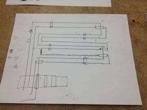
1. Plan
Sketch your circuit on paper and plan your components.

2. Test Your Prototype
The simplest way to test your prototype is to use a breadboard to roughly lay out your circuit, and make sure your circuit is performing as expected. Breadboards are convenient because there is no soldering required – everything is plug and play!
This example is taken from a nice writeup on Instructables.com about building circuit breadboards.
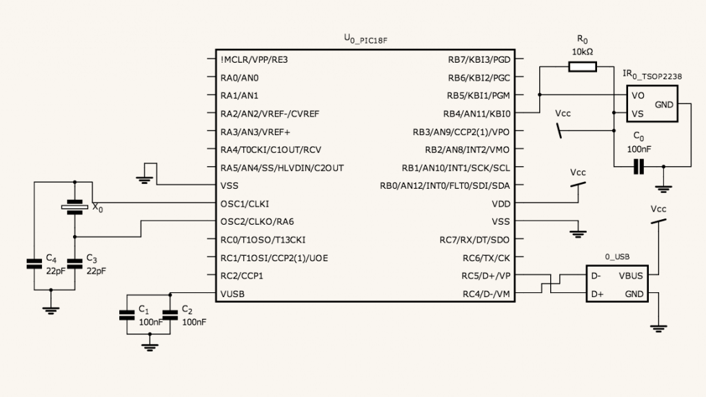
4. Design your circuit using Schematic Editor
There are several free PCB schematic editor solutions available (Express PCB, Free PCB, and a simpler, but very useful web-based option at Circuit.io), and for extremely complex or professional jobs, you may want to look for some higher-end paid solutions.
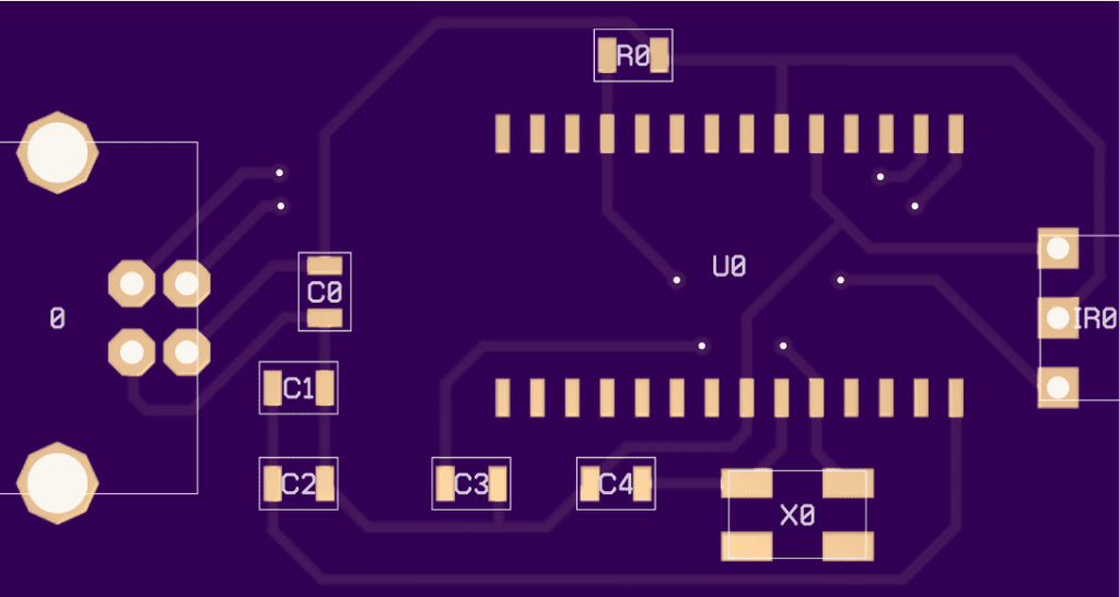
Sample Circuit.io circuit design: IR to USB Receiver

Circuit design:


