Creating a solid fabrication drawing for a wire harness or cable assembly is 100% key to having a successful and repeatable build. It is critical for the manufacturing of cable or wire harnesses that all requirements are properly documented. Requirements and best practices include these general items.
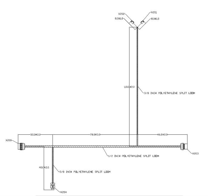
Wire Harness Physical Layout
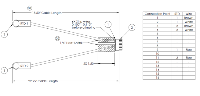
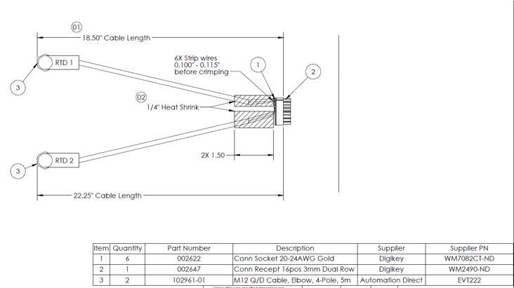
- Dimensions from locations that can be measured on a completed assembly (example: edge of connectors).
- Pinout of each connector.
- Colors can be very helpful and match with actuarial wire colors.
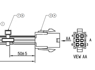
- 3rd angle projections of connectors are also very helpful.
- Dimensions of each overall wire bundle length.
- Length tolerances should be wide enough to be easy to manufacture+/-5% is great. (use a -0 tolerance if nominal length is the shortest acceptable)
- Overall dimensions of the wire or cable harness.
- Material callouts (example: ⅜ Inch Polyethylene Split Loom).
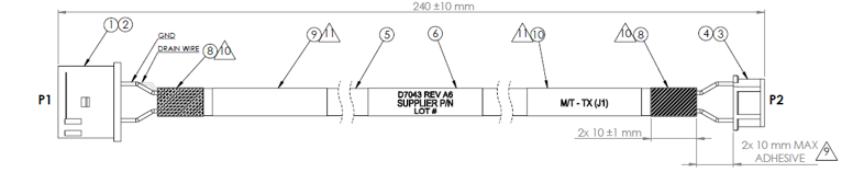
- Label locations.
- Dimensions should be from places which can be measured on a completed assembly (wire cut lengths are not very useful). We will 100% check these in final inspection.
- Specifying the pinout of the connector, especially with colors, is very helpful. Best practice is 3rd angle projection of the connector face.
- It should be clear where to measure dimensions from, like back of connectorend or end of connector
- Right angles are easiest to interpret but not always necessary.
Labels and heatshrink should appear on the drawing with dimensions and tolerances (or specified as “about” or “TYP”)
Specifying the pinout of the connector, especially with colors, is very helpful.
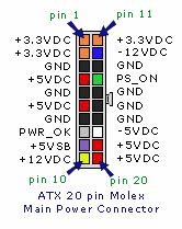
Best practice is 3rd angle projection of the connector face.
Routing Plan
- Components and Connections: Wire harness routing plans identify the specific electrical components, such as connectors, terminals, switches, and sensors, that need to be connected. They also indicate the type of connections required, including splices, push-in, crimps, or soldered joints.
- Wire Routes and Paths: The plans illustrate the routes that the wires and cables should follow from one component to another. This includes the physical locations, paths, and all required clearances or constraints to consider. This will allow the wires and wire bundles to avoid sharp edges, hot surfaces, or interference with other mechanical or electrical parts.
- Wire Identification: Each wire in the harness is usually labeled or color-coded for easy identification. The routing plans provide information about the specific wires, their functions, and the associated color or labeling scheme.
- Spacing and Bundling: Wire harnesses often contain multiple wires bundled together for aesthetics and ease of installation. The routing plans define how the wires should be grouped and bundled, specifying the diameter or size of the bundles, how the bundles will be secured together as well as the spacing between individual wires or bundles.
- Retention and Fixing Points: Wire harnesses need to be secured properly to prevent damage from vibration, shock, or environmental factors. The routing plans indicate the recommended fixing points, such as clips, brackets, or tie wraps, to ensure the harness is properly retained within the system.
- Serviceability and Maintenance: The plans may include provisions for easy maintenance and troubleshooting, such as access points, connector locations, or diagnostic test points, to facilitate future repairs or modifications.
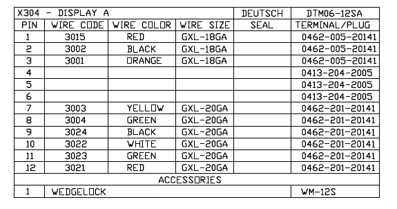
Pinout Tables
Pinout tables are easier to interpret than schematics, especially for larger harnesses. This is a great place to indicate different wire sizes, colors, types, and terminal types if that’s not obvious somewhere else on the print.
- Including cut lengths on this table is not necessary
- Connector pin numbers.
- Wire codes.
- Wire colors.
- Wire sizes (gauges).
- Terminal types.
- Seals
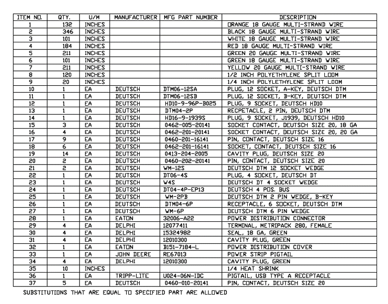
Bill Of Materials (BOMs)
Manufacturer part numbers for all components is ideal for all parts except where we stock generics like UL wire and heatshrink.
- Item numbers.
- Quantities.
- Units of measurements.
- Manufacturers.
- Manufacturers Part Numbers (MPN’s).
- Descriptions
Material Callouts
Best practice is to callout items numbers on the physical layout, usually with a circled BOM Item Number.
Fabrication Drawing Summary
It is important to note that the manufacturing process can vary greatly depending on many factors including but not limited to the complexity of the wire harness, size of individual wires, wire bundles and the overall size of the completed wire or cable harness. Industry requirements will also be a factor as applications for systems in automotive, aerospace, medical and other critical functioning applications might apply.