This great success story begins well over one year ago. On December 22, 2011, we were contacted by Viatemis of St Victor, France to quote 5 different part numbers. Part of the quote for this international customer was to quote the product both ocean and air to give them a precise look at the best option for saving money wherever possible if planned right. We quoted their projects that were budgetary; kept in communication over time and when the first project evolved into a prototype stage, it was not until April of 2013. Now, four months later, we are delivering the first of our flex circuits.
While these parts are fairly simple, the process of assisting in engineering the design for production was somewhat complicated but our factory engineer helped our customer fine tune their specifications for fabrication of this part. The process went smooth and of course, the product was extremely high quality.
Some notes from our internal engineer about assisting to help the flex circuit engineer – our customer (who did not have a lot of experience in flex) cover questions he was not able to answer his own questions.
1. Do you need the fiducial to realize the PCB or can I delete it? --> This is a question for the customer, but here is my input: The edge of the fiducial is right on the 4.2mm cutout, so there will be exposed copper. Also, the cutout will confuse the optics of the pick and place machine. Additionally, I do not know how a single fiducial could be useful in this application. My recommendation would be to remove it, unless there is some underlying reason to keep it.
2. Is the perpendicular angle is OK between the Flex part and the rigid part? --> I believe the issue here is the inside corner. There will need to be a radius here. Also, see my note about the rigid/flex on question 3 below, this may resolve this question.
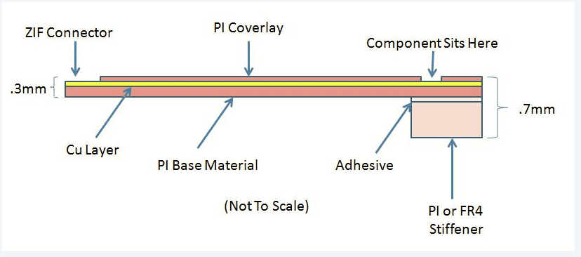
3. Does the component be too close from the rigid board? --> Yes, the part is close, about .6mm, but I do not think it is an issue. My interpretation of this part is not a rigid-flex, it is a single sided flex with a stiffener added to the non ZIF connector end. There is no electrical connection though the thicker part, so only one copper layer is involved, and that will all be on flex PI material. A stiffener would be added to the not copper side with adhesive. I drew up a quick cross sectional diagram to explain this. As the component will be on the opposite side of the stiffener, I do not see any manufacturing issues with its location. Increasing the stiffener size (8.00mm dimension) may help with assembly, but I do not know if it would affect the function of the flex circuit.
Our engineer worked with our factory engineer to wrap up the final design and we were able to proceed with a build. All the production engineering was complete within just a few short days. The customer then proceeded to order with a credit card and we pushed the order right into production. Our compliments to their very solid use of English in this project. Their exact comments to confirm the order:
Hello James,
We have just validate the investment for this flex PCB and we want to work with you. I’m filling the purchase order that you will receive soon. Have you got all the data to realize the PCB? I don’t remember if I send you all the files. Please be careful that we need the stiffener! I validate the investment with the price you give me without stiffener. Are you OK to realize the 10 first PCBs with this price? Can you please update the price for full production? Mrs. … will send you our UPS, Fedex, DHL account number.
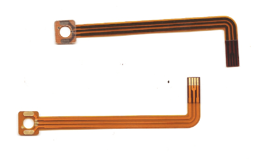
We received the following samples from our factory in China and are sending them out today.
Look no further if you need help with your next flex circuit board. We have been doing this for years and FEAR NOT if you don’t know enough about flex…we can help both from an engineering design and engineering for production perspective. Our design for manufacturing engineer has been designing flex boards for optimal manufacturing for more than 10 years. At the factory level we have been manufacturing these products for more than 13 years.
Give us a chance to produce your next flex or rigid flex PCB. We will surprise you with how smooth the project will go.
James Brown V.P. Sales & Marketing PCB Solutions, LLC info@pcb-solutions.com 866-517-9297


