Tesla Case Study for a Custom Flex Circuit
The Challenge
In the fall of 2022, Tesla’s sensor engineering team approached PCB Solutions requesting a 1-layer flex sensor inquiry.
Tesla’s team required the adhesive to be only on the back side of the flex layer in particular places. They also required traces that had to be exposed on the top side running 50-200um thick operating at temperatures with a range of 20 c to 100 c. Applied voltage would be 5 Vdc with current in the traces of 5uA.
Tesla also required a flex circuit that was 85 x 890mm long.
The Approach
Our team went right to work consulting in the design of a flex senor with a unique stack up consisting of an adhesive, PI (Polyamide) coverlay, conductive traces and a corrosion-resistant surface finish. PCB Solutions has unique capabilities for long flex circuits.
While most factories can only do the following:
- 1 Layer = 900mm
- 2 Layer = 780mm
PCB Solutions can do:
- 1 Layer = up to 1200mm with less limitation on the space and trace
- 2 Layer = up to 1200mm as long as the space and trace is ≥ 0.3/0.3mm
Options for exposed copper traces were discussed to meet the customer’s functional needs. Engineers concluded that Ni (as long as it was covered by Au) was a viable option with OSP being eliminated as it breaks down after 4-6 months.
In addition to the flex circuit, PCB Solutions assisted with the procurement, assembly, test and delivery of a full turn key build which included the following:
Section 1: TE MQS that had a small terminal, housing, and a wire housing. Section 2: Memcon (membrane switch) that had a crimp / pierce style terminal and housing. Section 3: A 1M Ohm resistor in a 0602 package.
Adding value to every possible project is what PCB Solutions does best. Our team quoted the flex board and its fabrication, component procurement, printed circuit assembly, wire harness assembly and surface mount assembly (SMT) operations.
Quoting Notes looked like this:
Quick notes:
- Production quoted and manufactured at our offshore facility in Southeast Asia.
- Material data sheets attached (sent to customer)
- Base Material
- 3M Adhesive
- ENIG Surface Finish – Engineering quoted ENIG vs exposed Nickel because of the Ni propensity to oxidize (especially electroless Ni). The Au will keep the traces non-corrosive for a much longer time. Typical thicknesses are:
- Electroless Ni = 100-120u”
- Immersion Au = 2u”
- Overall Thickness – Our engineers recommend 0.15mm +/- .05
- Quoted as an IPC Class III Project
Lead time and scope looked like this:
- 8 working days for the Flex PCB (once engineering questions are confirmed)
- 10 working days for the component’
sprocurement - 3-5 working days for the SMT component, membrane switch and wire placement / soldering
The Result
PCB Solutions assisted with the flex design and development of sensor that could be built at a reasonable cost and a quick turnaround. Our team quoted the flex sensor winning the bid for pricing, quality, complexity and delivery.
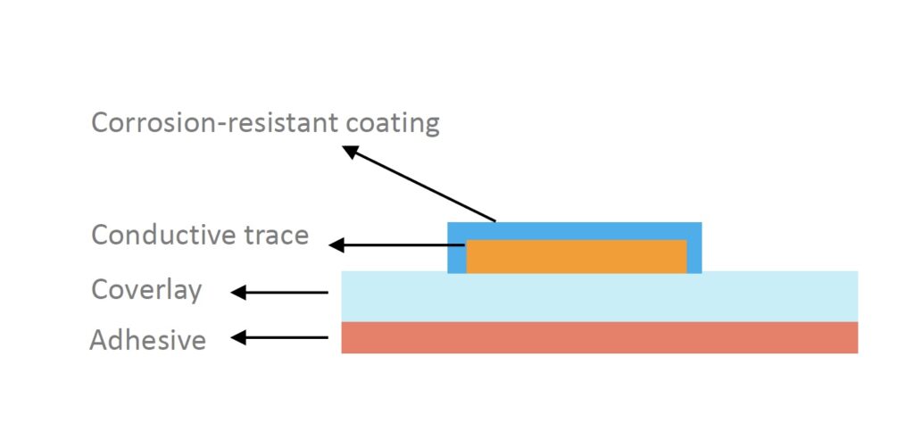
Initial stack up by the teams looked like this
- Adhesive
- Coverlay
- Conductive traves
- Corrosive resistant coatings

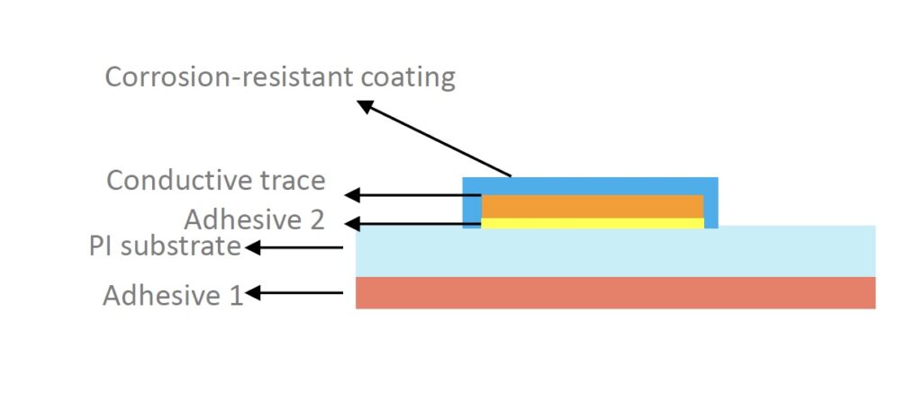
After an engineering review with design for manufacturing engineer (DFM), the next phased stack up look liked this.
Final stack up consisted of
- Adhesive one (3M Ultra High Temperature Transfer Tapes)
- PI Substrate
- Adhesive two
- Conductive traces
- Corrosive resistant coatings

An initial quantity of 50 pcs of the flex circuit board were ordered with a 30-day lead time, despite the Chinese New Year and a tight market for components. Our team was also awarded the assembly of the flex circuit to be built as full turn key solution.
We delivered the fully assembled project in the quoted lead time. The product tested well and the next steps are moving into pre-production assembly. Once production moves forward, PCB Solutions will implement In Circuit Test (ICT) and Function Test (FT) to ensure the delivery of high-quality circuit / assemblies in production quantities.
If you have a full turnkey project, please don’t hesitate to connect with our sales team


